Stepper Drivers
The printer uses various stepper motor drivers. This is because the ones included with the BTT Octopus board are not powerful enough to drive the NEMA 23 motors used for the X, Y, and Z axes. NOTE: Because the printer uses a Core-XY design, only two motors are used to control the X and Y axes simultaneously.
X & Y Axes
The X and Y axes motors are driven using higher-quality DM542T drivers from StepperOnline. These are capable of being run at 200 pulses/revolution, giving better response time than most stepper drivers.
Z Axis
The Z axis, which uses 4 stepper motors, could theoretically be controlled with a single driver by wiring all the steppers in parallel. However, this would not allow individual control of the steppers, which is required for convenient features like Klipper's bed tilt compensation. This feature is specifically for printers that have beds with 4 separate steppers, and allows the printer to correct for a non-flat bed by slightly adjusting the height of each corner. It's not yet known how useful this feature will be, but it could be a significant time saver when it comes to leveling such a large print surface.
Because the Z axis does not need as precise/fast motion control as the other axes, we used cheaper TB6600 stepper drivers instead.
Extruder
The extruder motor is small enough that we can use the TMC2209 stepper driversdriver included with the Octopus board.board is plenty powerful.
Voltage Levels
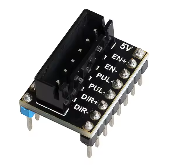
Both the DM542T and TB6600 drivers require 5 volt logic to operate. However, the Octopus board stepper outputs only use 3.3 volt logic. Because of this, logic-level converters are needed. I2C converters such as these are needed.adequate, BUT they are a massive pain to wire for all 6 motors. It appears that the "LERDGE" brand 3D printers use a similar setup with external stepper drivers, and so come with a level shifter breakout board that fits in the standard "Pololu" footprint that the Octopus board uses. While there was no way to confirm this from the AliExpress page, they do in fact have three transistors on the bottom half of the PCB that output 5V-shifted signals for DIR+, PUL+, and EN+, with the negative sides of each connected to ground. It also breaks out the 5V rail itself.
Connection to BTT Board
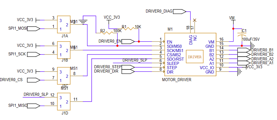
By default, the BTT board is designed to use integratedTMC stepper driverdrivers moduleswith thatthe can"Polulu" communicatequick-connect overfootprint. serial and have many extra features. Because we are using bare-bones drivers, we need to connectWe only threeuse jumpersa TMC driver board for the extruder motor, with the rest being connected to the motorabove ports:level EN,shifter STEP,breakout andboards. DIR.The schematic for the footprint on the Octopus board is below for reference.