Electronic Components
Electronic components used for the printer.
- Phaetus Rapido Hotend
- BigTreeTech Octopus Controller Board
- Stepper Drivers
- Voron StealthBurner Extruder + Hotend
- Raspberry Pi 4B
- BL-Touch
- ADXL345 Accelerometer
Phaetus Rapido Hotend
The printer currently uses a Phaetus Rapido for the hotend. It is the original model, not the Rapido 2, as it would have cost double the price for only a minor performance improvement. Additionally, the model purchased was the Ultra-high Flow model, which is identical to the standard model, except that it comes with an optional longer "volcano-style" hotend. Using the longer hotend would greatly increase flow rate, the standard Voron StealthBurner design does not account for the longer length and so it is currently not being used.
BigTreeTech Octopus Controller Board
The printer is controlled using the BTT Octopus 1.1 board. This board was chosen as it has many stepper motor outputs, allowing us to control up to 8 axis motors. The design files for the board are open source and can be found here, while the Klipper configuration details for the board are found on the Klipper page.
BLTouch
By default, the printer's Voron configuration doesn't use a BL-Touch probe and so isn't present on the diagram below (the "probe" mentioned is an inductive probe). See its respective page for details.
Wiring
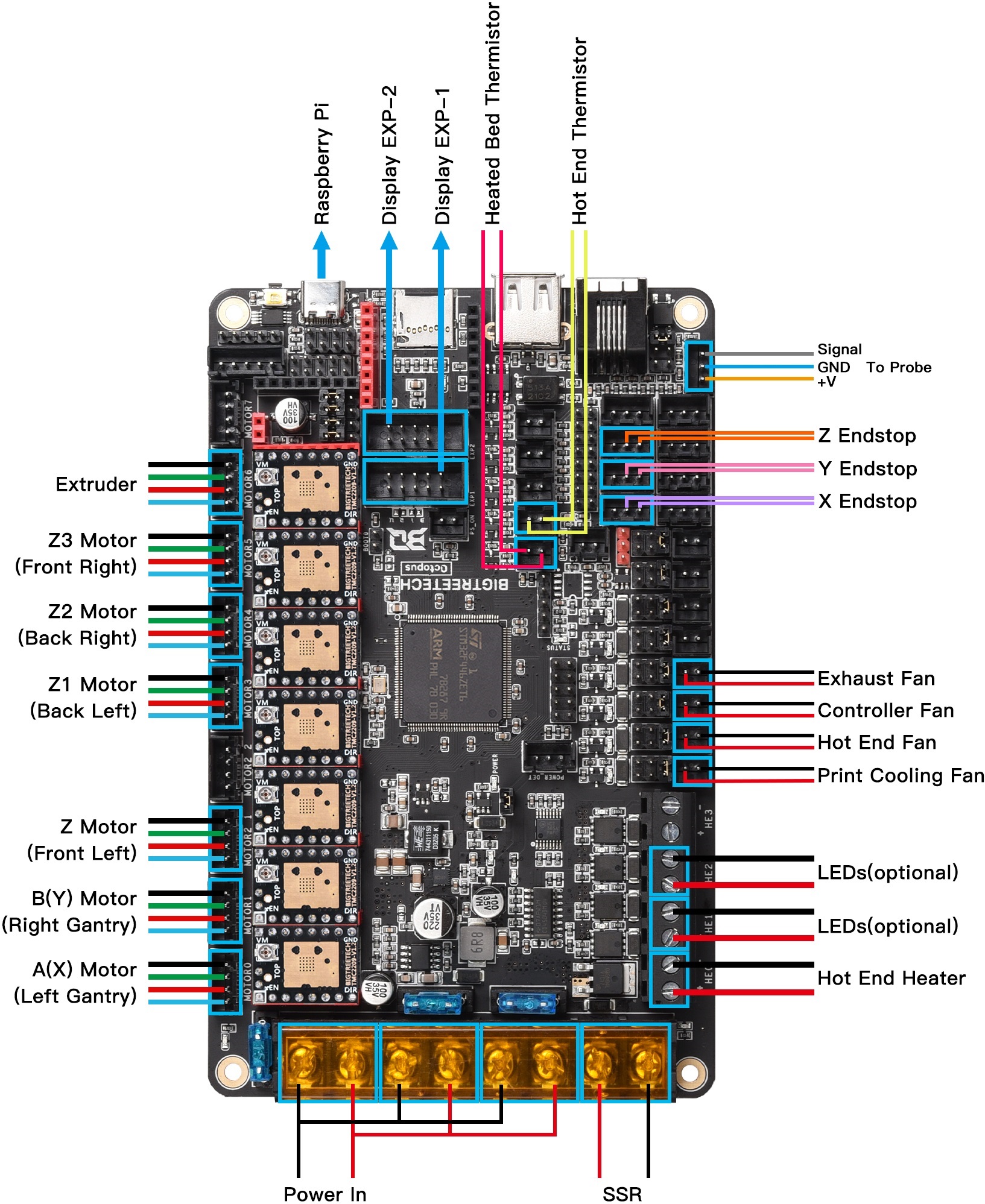
Info on wiring the board for a Voron 2.4 printer design can be found on this page. Its not clear whether the "Initial Preparation" steps are necessary if not using the provided firmware.bin file (which the board is currently NOT using). Farther down the page is the following wiring diagram, which may not match our configuration exactly, but is a great starting point:
Stepper Drivers
The printer uses various stepper motor drivers. This is because the ones included with the BTT Octopus board are not powerful enough to drive the NEMA 23 motors used for the X, Y, and Z axes. NOTE: Because the printer uses a Core-XY design, only two motors are used to control the X and Y axes simultaneously.
X & Y Axes
The X and Y axes motors are driven using higher-quality DM542T drivers from StepperOnline. These are capable of being run at 200 pulses/revolution, giving better response time than most stepper drivers.
Z Axis
The Z axis, which uses 4 stepper motors, could theoretically be controlled with a single driver by wiring all the steppers in parallel. However, this would not allow individual control of the steppers, which is required for convenient features like Klipper's bed tilt compensation. This feature is specifically for printers that have beds with 4 separate steppers, and allows the printer to correct for a non-flat bed by slightly adjusting the height of each corner. It's not yet known how useful this feature will be, but it could be a significant time saver when it comes to leveling such a large print surface.
Because the Z axis does not need as precise/fast motion control as the other axes, we used cheaper TB6600 stepper drivers instead.
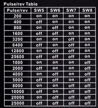
Microstepping
The external drivers support microstepping by way of the DIP switches on the side of the modules. The lowest resolution each stepper can achieve is 200steps/rev, which is no microstepping. Currently, all axis motors are set to 1/16 microstepping (3,200steps/rev) as the BTT Octopus board only supports 1/16 while also using a stepper driver with SPI as the extruder is. This is set on both the DIP switches and in the Klipper configuration file.
Extruder
The extruder motor is small enough that the TMC2209 stepper driver included with the Octopus board is plenty powerful.
Voltage Levels
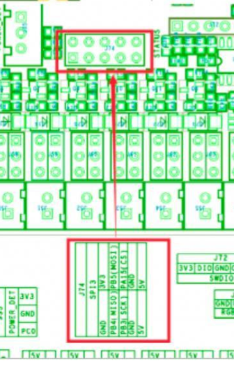
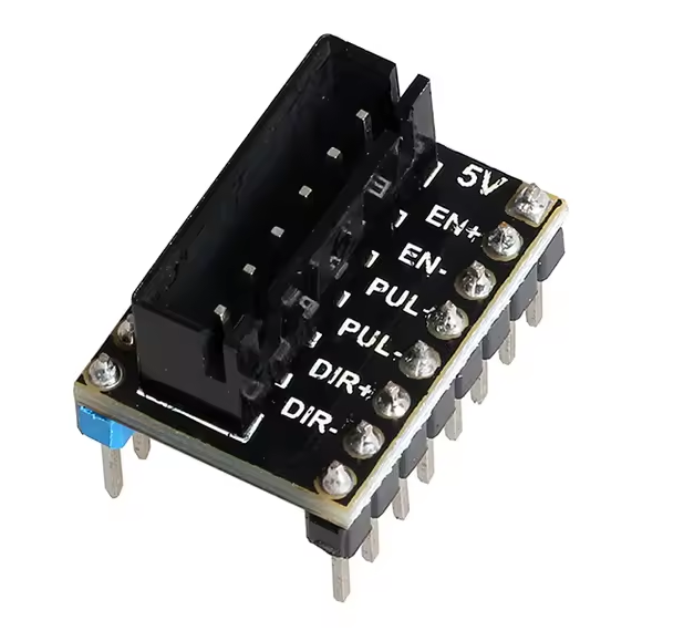
Both the DM542T and TB6600 drivers require 5 volt logic to operate. However, the Octopus board stepper outputs only use 3.3 volt logic. Because of this, logic-level converters are needed. I2C converters such as these are adequate, BUT they are a massive pain to wire for all 6 motors. It appears that the "LERDGE" brand 3D printers use a similar setup with external stepper drivers, and so come with a level shifter breakout board that fits in the standard "Pololu" footprint that the Octopus board uses. While there was no way to confirm this from the AliExpress page, they do in fact have three transistors on the bottom half of the PCB that output 5V-shifted signals for DIR+, PUL+, and EN+, with the negative sides of each connected to ground. It also breaks out the 5V rail itself.
Connection to BTT Board and Required Jumpers
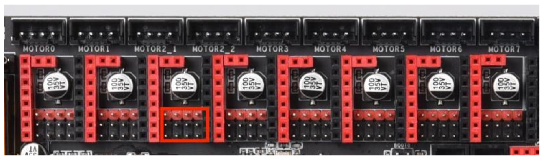
By default, the BTT board is designed to use TMC stepper drivers with the "Polulu" quick-connect footprint. We only use a TMC driver board for the extruder motor, with the rest being connected to the above level shifter breakout boards. Jumper pins need to be properly configured under each of the stepper driver modules (see pages 13 and 14 of the BTT Octopus manual):
For all external stepper drivers (X, Y, Z):
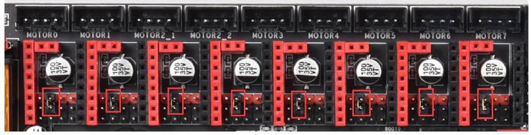
For TMC drivers in UART mode (currently just the extruder):
Voron StealthBurner Extruder + Hotend
The printer uses a Voron StealthBurner extruder, using a pre-made kit that contained all the various metal and electronic parts. The step-by-step guide to assembling the StealthBurner can be found here.
StealthBurner Printed Parts List (WIP)
The StealthBurner has many different configurations to accommodate different hardware. The following is a list of all parts we 3D printed for our assembly:
| Part File Name |
Variation Name |
GitHub Link |
|
[a]_stealthburner_main_body.stl |
Standard |
[click] |
|
sb_adxl_mount_generic_15.5mm_c_c.stl |
ADXL345 Mount |
[click] |
|
stealthburner_printhead_rapido_front.stl |
Phaetus Rapido Print-Head |
[click] |
|
stealthburner_printhead_rapido_rear_cw2.stl |
-- |
[click] |
Clockwork 2 Extruder
The StealthBurner has a modular design, and as such, the "Clockwork 2" extruder is available as either a Bowden or direct drive configuration. These files are kept in a separate folder on GitHub from the rest of the StealthBurner parts. All specified parts for the Clockwork 2 direct drive configuration were printed with no special changes.
The Clockwork 2 has a gear ratio of 50:10, which is set in the Klipper configuration file.
Raspberry Pi 4B
The printer is mainly controlled using a Raspberry Pi 4B computer running Raspberry Pi OS. On startup, the Pi should launch its own WiFi network that can be connected to with a laptop. The Pi is responsible for running Klipper and Mainsail, and is connected to the BTT Octopus board using a standard USB C cable.
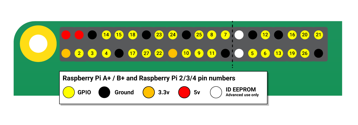
Power Button / Indicator LED
There is a script running that enables GPIO pin 3 to act as a power switch when connected to ground. See this page for more info, but in short, there is a momentary push button connected to GPIO 3 and GND which will shutdown the Pi when pressed.
According to this forum post, placing an LED across the TxD pin (GPIO 14) and GND will behave as a power indicator LED, lighting up when the Pi is on and turning off when it is safe to remove power.
BL-Touch
The BL-Touch is a physical bed leveling probe that the printer uses instead of the Voron's default inductive probe.
Klipper Config
The probe requires making some changes from the Voron configuration.cfg template, details of which can be found in the Klipper documentation here. These changes should mainly consist of:
- In the [stepper_z] section, set
endstop_pin: probe:z_virtual_endstop, and ensure there is noposition_endstopdefined. - Add the following sections:
[bltouch]
sensor_pin: ^PB_7   # white wire
control_pin: PB_6   # yellow/green wire

[safe_z_home]
home_xy_position: 457, 457 # Change coordinates to the center of your print bed
speed: 50
z_hop: 15                  # Move up 15mm
z_hop_speed: 5
Z-Offset Calibrate
To calibrate the probe's Z offset, use the PROBE_CALIBRATE command to start the procedure. Mainsail will then display a set of buttons that can be used to position the nozzle so that you can just barely push a 0.09mm (standard printer) piece of paper under the nozzle without it folding or bending, and then ACCEPT the new value.
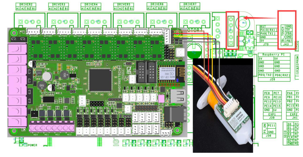
Wiring
The BL-Touch is connected to the Octopus board according to the diagram from here (note that the config information on that page is irrelevant as it is for the RepRap firmware which the printer does not use):
ADXL345 Accelerometer
The ADXL345 is a 3-axis accelerometer IC with built-in support from Klipper for calibrating the input shaping. It can communicate via both I2C and SPI, but the latter is generally recommended. The Octopus board has a header for SPI which makes configuration far easier as a second Klipper instance is required to use the Raspberry Pi's SPI pins. Because SPI is not designed for signal integrity, it becomes a problem when connected with long wires and surrounded by the EMI from large stepper motors. To address this, the ADXL is connected via a length of CAT5 Ethernet wire as recommended by the Klipper documentation. While SPI does not use a differential signal and so the benefits of using twisted-pair Ethernet wire are limited, it still made communication much more reliable than our first attempt using plain stranded wire.